There are several fields which bear on this question of physical simulation, including qualitative physics and structural mechanics, computer graphics, evolutionary design and robotics.
2.1 Qualitative Physics
Qualitative Physics is the subfield of AI which deals with mechanical and physical knowledge representation. It starts with a logical representation of a mechanism, such as a Heat Pump [7] or a String [8], and produces simulations, or envisionments, of the future behavior of the mechanism. QP has not to our knowledge been used as the simulator in an evolutionary design system.
2.2 Computer Graphics.
The work of Karl Sims [18], [19] was seminal in the fields of evolutionary computation and artificial life. Following the work of [16], Sims' evolved virtual creatures have both physical architecture and control programs created by an evolutionary computation process.
Despite their beautiful realism, Sims' creatures are far from real. His simulations do not consider the mechanical feasibility of the articulations between different parts, which in fact overlap each other at the joints, nor the existence of real world mechanisms that could produce the forces responsible for their movements.
2.3 Structural Mechanics/Structural Topology
The engineering field of structural mechanics is based on methods, such as finite element modelling [21], to construct computable models of continuous materials by approximating them with discrete networks. These tools are in broad use in the engineering community, carefully supervised and oriented towards particular product designs, and are often quite computationally intensive. Applications of genetic algorithms to structural topology optimization ([3], [17]) are related to our work. This type of application uses genetic algorithms as a search tool to optimize a shape under clearly defined preconditions. The GA is required, for example, to simultaneously maximize the stiffness and minimize the weight of a piece subject to external loads.
2.4 Evolutionary Design
Evolutionary Design, that is, the utilization of evolutionary computation techniques for industrial design, is a new research area where Peter Bentley's Ph.D. Thesis [2] is ground-breaking work. Bentley uses a GA to evolve shapes for solid objects directed by multiple fitness measures. His evolved designs include tables, prisms, even vehicle profiles.
Bentley's search algorithms use combinations of fitness measures ("Size", "Mass", "No Fragmentation", "Flat Upper Surface", "Supportiveness", etc.) that include some physical constraints, like center of mass positioning or total weight. Lacking a more complete physical model, he relies on specific measures to guide evolution in each case.
2.5 Evolutionary Robotics
Many researchers are working today on the evolution of control software for real robots. Evolutionary Robotics has become a field on its own [15]. Some rely on carefully designed simulations [4], while others apply evolution directly in the real robot [6]. Hybrid techniques [13] are a mixture of the two.
Lund, Hallam and Lee [11], [14] have evolved in simulation both a robot control program and some parameters of its physical body (sensor number and positioning, body size, etc.). Their last paper [14] addresses the possibility of co-evolving a robot controller and auditory morphology for the task of (cricket) phonotaxis. They contemplate the possibility of designing a Lego robot simulator.
3 The Physical Model
Simulation is the main problem for application of evolutionary techniques to real world problems. The actual world is too complex to be simulated, and frequently the `reality gap' between simulation and physical embodiment will drastically reduce the usefulness of what was simulated.
On the other hand, modelling is the tool that makes engineering possible. This means that Simulation is not wrong per se, and the formidable capacity for rapidly calculating the equations of a model is a defining property of our modern computers.
When it comes to modelling physical bodies, the continuum is source of both representational problems and uncomputability. Computational models of the world usually rely on a discretization of the elements being examined.
The resistance of the plastic material (ABS-acrylonitrile butadiene styrene) of Lego bricks far surpasses the force necessary to either join two of them together or break their unions. This makes possible for a model to obviate the resistances of the material and consider the strain forces over a group of bricks as acting only at their union areas. If a Lego structure will break, It will do so at the unions, but the actual bricks will not be disrupted.
This characteristic of Lego structures makes their discretization for modelling an obvious step. Instead of imposing an artificial mesh for simulation purposes only, these structures are already made of relatively large discrete units.
3.1 Description of the model
Based on elementary statics of rigid bodies, our model considers the union between two bricks as a rigid joint between the centers of mass of each one, located at the center of the actual area of contact between them (fig 1). This joint has a measurable torque capacity. That is, more than a certain amount of force applied at a certain distance from the joint will break the two bricks apart. The fundamental assumption of our model is this idealization of the union of two Lego bricks together.
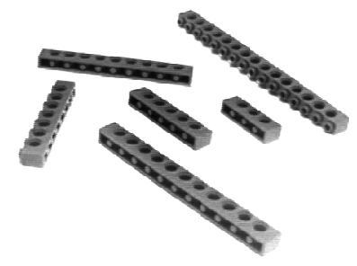
Only two-dimensional systems of forces have been considered so far. Using the family of Lego bricks of width 1 available at our lab (fig. 3.) we can consider complex 2-dimensional combinations of bricks and model them as a superimposed system of point masses joined together with a network of rigid joints (fig. 9.).
We have measured the resistance of such joints to external forces and torques and simplified the model to consider only the torques being applied at the joint. The resistance to radial forces is considered infinite. Our measurements indicate that even the weakest type of joint can support a relatively big load when it is applied radially only, with zero torque. Our next generation simulator will probably incorporate these forces for an improved model.
Table 1. resumes our measures of the torque capacities of the Lego joints we use.
Table 1. Estimated minimal torque capacities of the basic types of joints
These measures are relative: They vary from one brick to another, and by undetermined factors such as temperature, humidity, aging, etc. The table shown reflects an attempt at taking a conservative measure: The number we need to use is the minimum that any Lego union of certain characteristics is guaranteed to support and not, for example, the average.
In our simulations we used the conservative figures above and additionally set the gravitational constant to 1.2 times its actual value - thus allowing for an extra 20% error margin.
Our model of `rigid' joint means it will exert any reaction torque necessary to avoid breaking, up to a certain limit. All we are using is this concept of a maximum load. In a stable system, the actual torque being exerted by certain body at any given joint is underdetermined.
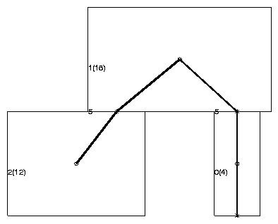
This means for example that if two bricks are supporting the weight of a third one between them (fig. 2.), the load could be considered to be distributed among each of the two joints in any legal combination. Since only one joint is enough in this case, we could consider that all the weight is on the left joint, and none on the right one. This can be verified by removing the right supporting brick: The middle one will not fall, because the union with the leftmost brick is strong enough to support its weight.
Our model is thus based on the following principle: As long as there is a way to distribute the weights among the network of bricks such that no joint is stressed beyond its maximum capacity, the structure will not break.
The algorithmic rendering of our model is still under development. However, it allows us to make the model calculations and obtain the results we are presenting. However, even in its initial state, it worked well enough to use as a basis for fitness testing of structures which were indeed buildable.
This algorithm must find whether or not there exists a distribution of the combined gravitational forces generated by the center of mass of each brick, such that no joint is stressed beyond its maximum capacity.
For each given brick we consider the network of all the joints in the structure as a flow network that will absorb this weight and transmit it to the ground. Each joint can support a certain fraction α of such a force, given by the formula
for each body b and joint j, where Kj is the maximum capacity of the joint, dx(j,b) is the distance between the body and the joint along the horizontal axis, and wb the weight of the body.
If a given body b is fixed and each edge on the graph on fig. 9. is labeled with the corresponding aj,b according to (1), a network flow problem ([5], chapter 27) is obtained where a net flow of 1.0 between a source b and the two sinks at (5,0) and (20,0) represents a valid distribution of the weight of b in the structure.
The complete problem is not reducible, however, to a network flow algorithm, due to the fact that there are multiple forces to be applied at different points, and the capacity of each joint relative to each body varies with the mass of the body and the x-distance between body and joint.
Leaving aside the study of better algorithmic implementations, we have simply implemented a greedy algorithm: Once a solution has been found for the distribution of the first mass, it is fixed, and a remaining capacity for each joint is computed that will conform a reduced network that must support the weight of the next body, and so on.
The fundamental consideration to be done here is that, even if our algorithm does not find all possible solutions, it finds many of them. Any structure that is `approved' by our simulation possesses a load distribution that does not overstress any joint, and thus it will not fall under its own weight. It will stand. Our evolutionary algorithm might be limited by the simulation when it fails to approve a structure that was physically valid, but still may succeed by working only in the space of `provable' solutions.
A second compromise in our simulation will come from the fact that our initial implementation of the simulation algorithm does not scale well. Its worst case running time would be O(3n), where n is the number of bricks. Fortunately, in the actual examples, many bricks are connected only to one or two others, thus reducing the number of combinations.
Again this combinatorial explosion problem will ultimately constrain the search space. Only the solutions that can be found by our algorithm in a reasonable time are useful to our evolutionary runs.
We inserted an ad hoc limiting parameter into our code to cut off the simulation when it has failed to find a solution after a certain maximum number of iterations.
Our initial representation to perform evolutionary computation over these structures borrows the standard tree mutation and crossover operators from genetic programming [10]. We have implemented a tree notation for two-dimensional Lego structures. Each node on the tree represents a brick and has one size parameter (either 4, 6, 8, 10, 12 or 16 for the available brick sizes) and four potential sons, each one representing a new brick linked at one of its four corners. When a union is present, a joint size parameter determines the number of overlapping knobs in the union.
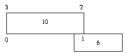
The diagram on fig. 4. represents a 10-brick with its 4 joint sites labeled 0, 1, 2, 3, that is linked to a 6-brick by two overlapping knobs. The corresponding tree could be written in pseudo-Lisp notation as
(10 NIL (2 (6 NIL NIL NIL)) NIL NIL) (2)
A problem with this representation, similar in origin to the problem of valid function parameters in genetic programming, is that it is underconstrained: Only some trees will encode valid Lego structures. No more than one brick can be at each corner, so every node can have at most three sons, not four as the encoding allows. Joint sizes must also be compatible with each other and in general, two bricks cannot overlap each other. The following extension to (2), for example, is illegal because both 10-bricks would share the same physical space
(10 NIL (2 (6 NIL NIL NIL (4 (10 NIL NIL NIL)))) NIL NIL) (3)
There are two possible mutations:
To implement mutation, a random joint in the tree (or the root) is selected, and, if NIL, mutation 2 is applied, otherwise mutation 1.
Crossover, in turn, Regarding crossover, the basic crossover operator involves two parent trees out of which random subtrees are selected. The offspring generated has the first subtree removed and replaced by the second.
After mutation or crossover operators are applied, a new, possibly invalid specification tree is formed. The resulting is expanded one node at a time and overlapping is checked. Whenever an overlap is found the tree is truncated at that site.
With this procedure, a maximum spatially valid subtree is built as the result of crossover or mutation.
Once a valid tree has been obtained, the physical model is constructed and the structure tested for gravitational correctness. If approved, fitness is evaluated and the new individual is added to the population.
Our goal is not to optimize the evolutionary algorithm, but to show that evolution is indeed possible and our models are physically sound. We use a straightforward steady-state genetic algorithm:
These are the basic parameters used in the GA runs:
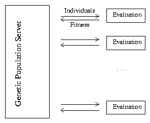
We are using a parallel version of this algorithm that runs on an SGI Onyx, a 16 processor MIMD machine. Our parallel GA is asynchronous, that is, each processor iterates independently over steps 1 through 7, without any synchronization states.
Fitness evaluations are the interface between a learning evolutionary algorithm and its environment. In complex, dynamic scenarios, fitness evaluations are time consuming. In many cases -imagine a GA having to generate a control program for obstacle avoidance in a robot- a fitness evaluation can be several orders of magnitude slower than the underlaying GA. Algorithms are then required that may run hundreds of parallel fitness assays independently, without synchronizing before the next round.
Our algorithm conceives the population as a genetic server that feeds individuals to all available evaluators and receives fitness values from them. This type of algorithm can run on parallel MIMD machines as well as computer networks where different machines evaluate data for a central genetic engine.
For each experiment below we prepare a custom fitness function that will serve both as a measure for the evolutionary selection process and as a tag that reflects our interest in a computer generated structure. When our algorithm finds a new maximum fitness, it saves this 'champion' and offers it as a new and improved candidate solution for the problem.
Throughout the experiment reported in this paper, fitness values have been a combination of three measures:
We demonstrate the effectiveness of our evolutionary structure and Lego simulator on a set of fitness cases resulting in useful computer designed structures.
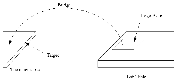
The goal of our first experiment was to evolve a structure to go over from one table to another in our lab.
Consider a big Lego square plate fixed to the edge of a table in our lab. Our simulation will permit us to predict wether or not a linear structure, made of our family of Lego bricks which starts at the edge of the table and projects itself without any additional support towards the table on the opposite side of the lab, will collapse under its own weight or not.
Our fitness function was set to be the normalized distance from the object to the target point, at Lego coordinates (150,0).
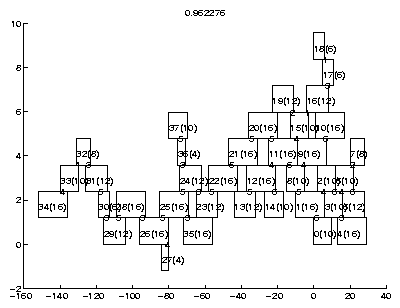
Our initial results were encouraging. The genetic algorithm reliably builds a structure that goes up and away from the launching base and then has to lower the tip of the structure to get to the target point.
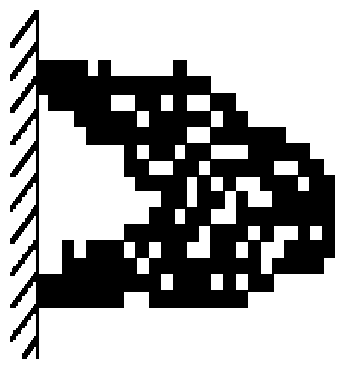
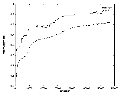
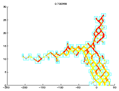
An example successful run is presented in fig. 8., fig. 9. and the picture of the resulting built Lego bridge in fig. 7. The target fitness of 0.96 was reached after 133,000 generations(2).
The following is a graph of maximum and average fitness values over the run which produced the previous model:
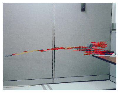
Bouyed by our initial success, in our second experiment we used our parallel implementation and left the algorithm running a whole week to see how large a self-supporting structure we could obtain.
The fitness measure for this experiment is just the length, or stretch over the table measured along the x axis. We had to use an iteration cutout to prevent overly complex designs from slowing down our network flow algorithm. Our program thus rejects potentially correct structures when the fitness evaluation takes too long.
After 3,240,000 generations the structure evolved was 1.67 meters long (207 Lego units), made out of 97 bricks.
This experiment reveals one of the limitations of the model. The structure shows an appreciable downwards bending that was not considered in it.
On the other hand, assuming that the model is correct, it is not possible to do much better than our algorithm did. Analysis showed that the height of a minimal self-supporting structure grows exponentially with length.
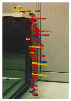
After working with bridges, we decided we might meet a scaffold. Evolve a structure growing along the y axis instead of, from the top of the table down to the floor.
The fitness measure was set to be the distance from the object to a target point in the floor, 0.76 m below the table surface.
The answer was found very quickly. The structure has an alien look but does the job. It evolved in 40,000 generations.
In the `crane' experiments we applied our evolutionary environment to a practical problem: To build the arm of a crane which could carry a load. This is our first experiment in designing a structure which would withstand some dynamics of Lego movement when actually built.
A general crane base was designed providing a motor and a stand base for the arm. Two identical parallel arms are needed to hold an axle at the tip from which the hook will hang.
The algorithm should try to find an arm as strong as possible, given the imposed restrictions. To build the crane we use two arms, with the added benefit of doubling the maximum load.
The fitness function was designed to reward having a brick in the right place (.5 m from the base), and for carrying as much weight at the tip before breaking.
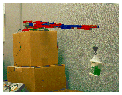
A crane arm was found that supports a cargo of 92g. Combining two arms we obtained a crane (fig. 14.) that supports a maximum weight of 180 grams at the tip.
We were not able to evolve a crane arm as strong as we imagined. Later analysis showed that the arm obtained is indeed optimal (given our model), because it uses the maximum torque provided by the base on which we want the arm to attach. No matter what shape, no arm could overcome this externally imposed limitation.
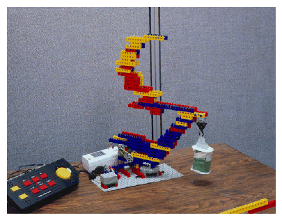
In the same spirit as the previous experiment, we added a degree of freedom making our first "3d" design. The rotating crane also consists of a human design that provides the evolutionary algorithm with a sufficient set of constraints so as to guarantee that the evolved structure will be useful.
In this case we designed a rotating base with a motor to pull from a hook. A diagonal arm has to be evolved, providing height and strength for lifting heavy loads.
The fitness measure used was a combination of the length of the arm and the maximum load supported at the tip. Restrictions were imposed to match the base we designed and to force the arm to grow diagonally.
We obtained a crane that would support a weight of 250 grams at a height of 19.2 cm. and a distance of 16 cm.
It was interesting to observe how a counterweight structure was evolved, but located at the top, not the base as in real cranes. This is the structure that we actually built for the crane shown in fig. 15. Subsequently a stronger and much bigger structure was found in which the counterweight "touched down" and attached itself to the base.
The greedy algorithm for assigning partial torques is the first pass using a somewhat limited understanding of the statics involved. Lego, with its sticking force, is a lot more complex to simulate than simple building blocks, but we have not fully exploited all possible efficiencies. As it stands (sic) the algorithms appears to be equivalent to a multi-commodity flow problem, which in certain cases is NP-complete ([9], [12]).
Secondly as a first pass, our simulator is quite limited. We are working to move to the third dimension with a greater variety of blocks, and some understanding of the dynamic stresses which would be involved in basic Lego mechanisms driven by Lego motors. This would open the field for evolving active pieces of machinery, including vehicles.
Thirdly, our basic steady-state GA, and our parallel model are elementary approaches which do not take into account many of the advances in the fields of evolutionary computation. The weakness of our tree representation, which generates many infeasible solutions, is apparent, and the need for modular configurations of blocks, such as the well-known bricklayers patterns, which hold increased stresses ought to be extractable from our learning algorithms as modular components which survive selection [1].
We have shown that under some constraints, a simulator for objects can be used in an evolutionary computation, and then the objects can be built. This is a little different from evolving controllers for existing robots, and is a step on the way to the full co-evolution of morphology and behavior we believe is necessary for the development of robots and brains of higher complexity than humans can engineer.
By keeping inductive biases and ad hoc ingredients to a minimum, we believe that we have only scratched the surface of what is achievable. If we can reach the 3-d version and provide limited dynamics simulation, we will have opened the door to many possibilities and created a new and fertile area for evolutionary machine research.
[7] Forbus, K. (1984). Qualitative process theory. In Artificial Intelligence 24, 85-168.
[18] Sims, K. (1994) Evolving Virtual Creatures. In Computer Graphics, Annual Conference Series.
        ------------------------------
             Joint       Approximate
        size(knobs)     torque capacity
                          (N-mx10-6)
        ------------------------------
              1              10.4
              2              50.2
              3              89.6
              4             157.3
              5             281.6
              6             339.2
              7             364.5

        ------------------------------
3.2 A Greedy Generalized Network Flow Algorithm
3.3 Time complexity
4 Representation
4.1 Mutation and Crossover
1. Mutation of the joint and brick sizes at any random point
2. Addition of a single brick at a random empty joint
4.2 Steady State GA with low evolutionary pressure.
        1.  While maximum fitness < Target fitness
        2.  Do  Randomly select mutation or crossover.
        3.      Select 1 (2 for crossover) random individual(s)
		    with fitness proportional probability.
        4.      Apply mutation or crossover operator
        5.      Generate physical model and test for gravitational load
        6.      If the new model will support its own weight.
        7.          Then replace a random individual with it.(chosen with
			inverse fitness proportional probability)
4.3 Parallel Asynchronous GA
5 Results
1. Length (in a certain direction). We use this fitness measure when the structure wanted has to be as long or as big as possible, given or not other constraints.
2. Normalized distance to a target point.To avoid an inverse (the smaller the better) fitness, when the algorithm is trying to reach a fixed point we use 1-(distance from structure to target)/(distance form (0,0) to target) as a normalized measure in the range (0,1).
3. Supportiveness.To maximize the external weight that a structure can support, we divide the maximum load supported by a candidate by the target supportiveness we are trying to obtain. This is a fitness measure in the interval (0,1)
5.1 The Bridge


5.2 Long Bridge
5.3 Scaffold
5.4 Crane Arm
5.5 Rotating Crane Arm
6 Future Work
7 Conclusions
References
Footnotes
 (1)
(1)